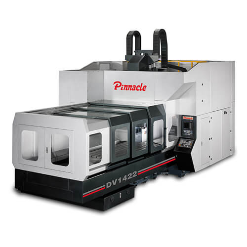
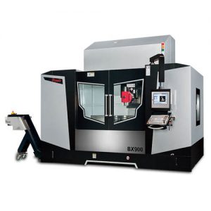
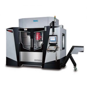
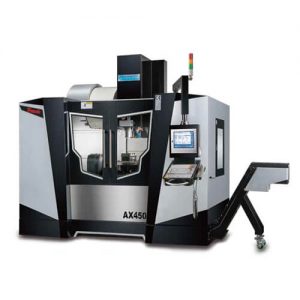
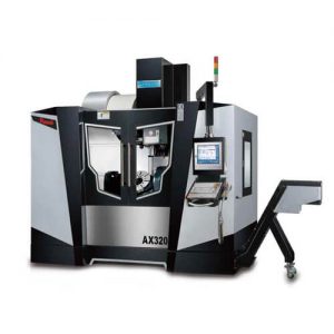
DV14/DV17/DV19/DV21
Double Column Machining Center

Double Column Machining Center:
DV14 series Double Column Machining Center that fully combines heavy cutting and high-speed machining capabilities in one. The DV14 series is a profitable performer, especially excellent for precision machining for extra heavy parts. To ensure maximum stability when handling heavy parts machining, the five major structural parts of the machine are manufactured from high-quality Meehanite cast iron and ductile iron. The specially designed machine structure enables the machine to keep at the best accuracy condition after years of operation. With the roller-type linear guideways on the X, Y, and Z axis, the machine fully exhibits its heavy loading resistance and outstanding features.

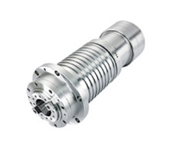
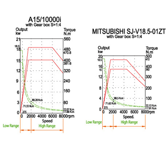
To meet the high-speed, high-precision machining requirement, the DV14 series employs a direct-drive high-speed spindle. This combines with a high/low-speed gearbox for transmission with a wide speed range. It makes the machine ideal for high-speed machining. In addition, the gearbox also provides high torque output, permitting the machine to perform heavy cutting with ease. The spindle head on the DV14 series is designed with an advanced automatic compensation balancing system combined with the use of an accumulator to control the hydraulic cylinder, allowing the spindle to move smoothly and steadily at all times.

Features

ROLLER TYPE LINEAR WAYS ON THREE AXES
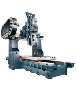
  • All major structural parts are manufactured from high quality cast iron with tempering tread to relieve stress, ensuring maximum material stability without deformation.
  • Box type structural parts are rib reinforced to increase structural strength and rigidity.
  • Extra heavy base complete support of table and resists heavy load without deformation.
  •   X, Y, Z axis are mounted with roller type linear ways combined with extra wide between ways for added stability.

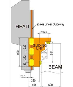
RIGID SPINDLE HEAD
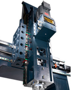
  • The spindle head is a box-type construction that increases stability when performing heavy loading.
  • The linear ways on Z axis are specially designed with side layout to upgrade rigidity of the spindle head.

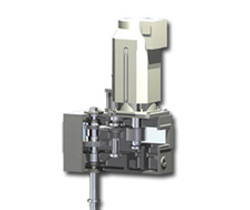
GEAR BOX
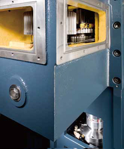
  • This spindle running is transmitted through a gear box, making the machine excellent for heavy cutting applications.
  • Wide spindle speed range from 10 to 6,000 rpm permit the machine to perform heavy cutting and fine finishing.
  • All gears and bearings in the gear box are oil-bath lubricated.

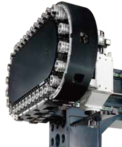
32 TOOLS CHAIN TYPE MAGAZINE (STANDARD)
  • The magazine is driven by a precision cam, featuring fast and accurate tool positioning.
  • Tool selection is bi-directional and random for fast tool change.
  • The magazine accepts ISO 50 tool shank.
  • The magazine is separately mounted from the cutting area combined with a protection door to prevent tools contamination from chips or coolant.


GEAR BOX

SPINDLE


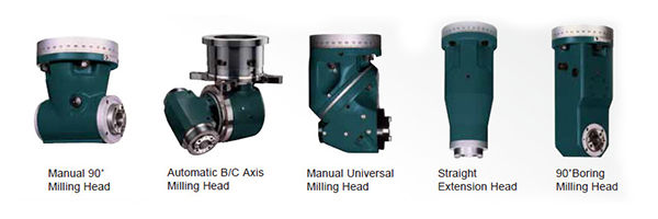
CHOICE OF VARIOUS MILLING HEADS

THESE MILLING HEADS ARE OPTIONAL

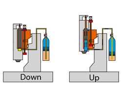
PNEUMATIC BALANCE ON Z-AXIS

The Z-axis movement is counter-balanced through a pneumatic counter-balance system. An accumulator is equipped in the air circuit, ensuring fast and stable movement of Z-axis.

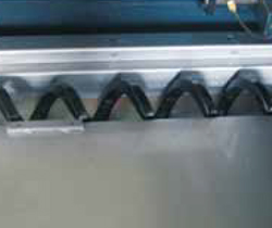
TWO SCREW TYPE CHIP CONVEYORS ON BASE

There are two screw type chip conveyors provided at right and left side of the base. During cutting, the chips are delivered through these chip augers to a chip conveyor for exhausting chips outside the machine.

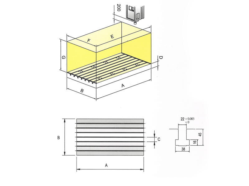
WORK RANGE / TABLE SIZE
A B C D E F G
DV1417 1700 1200 150 150 1700 1200 900
DV1422 2200 1200 150 150 2200 1200 900
DV1432 3200 1200 150 150 3200 1200 900
DV1442 4200 1200 150 150 4200 1200 900

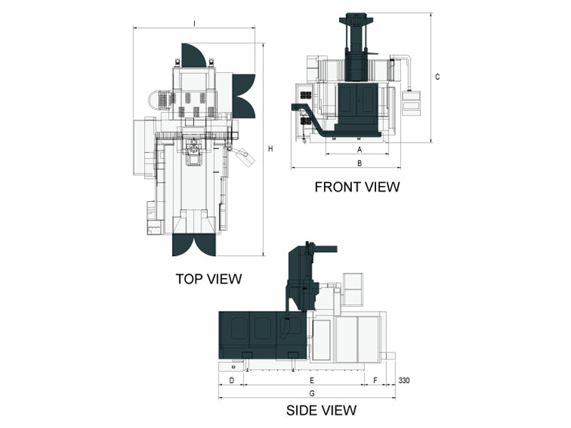
FLOOR SPACE
A B C D E F G H I
DV1417 2210 3816 4420 1995 4100 856 7254 8600 5700
DV1422 2210 3816 4420 1995 4100 856 7254 8600 5700
DV1432 2210 3816 4420 1995 6100 1200 9598 10640 5700
DV1442 2210 3816 4420 1995 8100 1550 11948 13300 5700

Specifications

MODEL DV1417 DV1422 DV1432 DV1442
TRAVEL
Travel Ranges (X x Y x Z mm) 1700 x 1400 x 900 2200 x 1400 x 900 3200 x 1400 x 900 4200 x 1400 x 900
Spindle Nose to table Surface (mm) 160~1060 160~1060 110~1010 110~1010
Spindle Center to Column (mm) 404 404 404 404
Distance between Column (mm) 1400 1400 1400 1400
TABLE
Table Size (mm) 1700 x 1200 2200 x 1200 3200 x 1200 4200 x 1200
T Slot  (W D x N mm  ) 22 x 150 x7 22 x 150 x7 22 x 150 x7 22 x 150 x7
Max. Table Load (kg/m2) 5000 5000 8000 8000
SPINDLE
Tool Shank & Pull Stud ISO50 ISO50 ISO50 ISO50
Spindle Inner Diameter (mm) Ø100 Ø100 Ø100 Ø100
Spindle Speed (rpm) Gear 8000 8000 8000 8000
Draw Bar Force (Kgf) 1800 1800 1800 1800
Main Motor (con/30 min Kw) 15/18.5 15/18.5 15/18.5 15/18.5
AXIS SERVO MOTOR
Rapid Feed Rate (X/Y/Z m/min) 20/20/20 16/20/20 16/20/20 12/20/20
Feed Rate (X/Y/Z/ mm/min) 10000 10000 10000 10000
Mitsubishi (X/Y/Z/ kW) HF703 7.0 HF703 7.0 HF703 7.0 HF703 7.0
Fanuc α 30/3000i 7.0 α 30/3000i 7.0 α 30/3000i 7.0 α 30/3000i 7.0
Siemens 1FK7 103 7.0 1FK7 103 7.0 1FK7 103 7.0 1FK7 103 7.0
Fagor FXM75.20 7.0 FXM75.20 7.0 FXM75.20 7.0 FXM75.20 7.0
Heidenhain QSY 190D 9.6 QSY 190D 9.6 QSY 190D 9.6 QSY 190D 9.6
AUTO TOOL CHANGER
ATC Type DISK / Chain DISK / Chain DISK / Chain DISK / Chain
Cam Type Arm Arm Arm Arm
Tool Selection (Bi-direction) Random Random Random Random
Tool Storage Capacity (PCs) 24/32 24/32 24/32 24/32
Max. Tool Diameter (mm) Ø110/ Ø125(Ø160/ Ø250)
Max. Tool Length 350
Max. Tool Weight 20
MISCELLANEOUS
Air Requirement (Kg/cm2) 6 6 6 6
Hydraulic Requirement (Kg/cm2, L) 60, 40L 60, 40L 60, 40L 60, 40L
Voltage 220 220 220 220
Power Requirement (KVA) 50 50 50 50
Coolant Tank Capacity (L) 900 900 900 900
Machine Weight (KGs) 15500 16000 17000 18000
Machine Height (mm) 4500
Floor Space (L x W mm) 5800 x 4150 6090 x 4150 8130 x 4150 10310 x 4150
MODEL DV1722 DV1732 DV1742
TRAVEL
Travel Ranges (X x Y x Z mm) 2200 x 1700 x 900 3200 x 1700 x 900 4200 x 1700 x 900
Spindle Nose to table Surface (mm) 160~1060 110~1010 110~1010
Spindle Center to Column (mm) 404 404 404
Distance between Column (mm) 1900 1900 1900
TABLE
Table Size (mm) 2200 x 1500 3200 x 1500 4200 x 1500
T Slot  (W D x N mm  ) 22 x 150 x 9 22 x 150 x 9 22 x 150 x 9
Max. Table Load (kg/m2) 8000 10000 12000
SPINDLE
Tool Shank & Pull Stud ISO50 ISO50 ISO50
Spindle Inner Diameter (mm) Ø100 Ø100 Ø100
Spindle Speed (rpm) Gear 8000 8000 8000
Draw Bar Force (Kgf) 1800 1800 1800
Main Motor (con/30 min Kw) 15/18.5 15/18.5 15/18.5
AXIS SERVO MOTOR
Rapid Feed Rate (X/Y/Z m/min) 16/16/20 16/16/20 12/16/20
Feed Rate (X/Y/Z/ mm/min) 10000 10000 10000
Mitsubishi (X/Y/Z/ kW) HF703 7.0 HF703 7.0 HF703 7.0
Fanuc α 30/3000i 7.0 α 30/3000i 7.0 α 30/3000i 7.0
Siemens 1FK7 103 7.0 1FK7 103 7.0 1FK7 103 7.0
Fagor FXM75.20 7.0 FXM75.20 7.0 FXM75.20 7.0
Heidenhain QSY 190D 9.6 QSY 190D 9.6 QSY 190D 9.6
AUTO TOOL CHANGER
ATC Type DISK/CHAIN DISK/CHAIN DISK/CHAIN
Cam Type Arm Arm Arm
Tool Selection (Bi-direction) Random Random Random
Tool Storage Capacity (PCs) 24/32 24/32 24/32
Max. Tool Diameter (mm) Ø110/ Ø125
(Ø160/Ø250)
Ø110/ Ø125
(Ø160/Ø250)
Ø110/ Ø125
(Ø160/Ø250)
Max. Tool Length 350 350 350
Max. Tool Weight 20 20 20
MISCELLANEOUS
Air Requirement (Kg/cm2) 6 6 6
Hydraulic Requirement (Kg/cm2, L) 60, 40L 60, 40L 60, 40L
Voltage 220 220 220
Power Requirement (KVA) 50 50 50
Coolant Tank Capacity (L) 900 900 900
Machine Weight (KGs) 21000 22500 24000
Machine Height (mm) 4500 4500 4500
Floor Space (L x W mm) 6090 x 5300 8130 x 5300 10310 x 5300
MODEL DV1922 DV1932 DV1942
TRAVEL
Travel Ranges (X x Y x Z mm) 2200 x 1900 x 900 3200 x 1900 x 900 4200 x 1900 x 900
Spindle Nose to table Surface (mm) 160~1060 110~1010 110~1010
Spindle Center to Column (mm) 404 404 404
Distance between Column (mm) 1900 1900 1900
TABLE
Table Size (mm) 2200 x 1700 3200 x 1700 4200 x 1700
T Slot  (W D x N mm  ) 22 x 150 x 11 22 x 150 x 11 22 x 150 x 11
Max. Table Load (kg/m2) 8000 10000 12000
SPINDLE
Tool Shank & Pull Stud ISO50 ISO50 ISO50
Spindle Inner Diameter (mm) Ø100 Ø100 Ø100
Spindle Speed (rpm) Gear 8000 8000 8000
Draw Bar Force (Kgf) 2000 2000 2000
Main Motor (con/30 min Kw) 15/18.5 15/18.5 15/18.5
AXIS SERVO MOTOR
Rapid Feed Rate (X/Y/Z m/min) 12/16/20 12/16/20 10/16/20
Feed Rate (X/Y/Z/ mm/min) 10000 10000 10000
Mitsubishi (X/Y/Z/ kW) HF703 7.0 HF703 7.0 HF703 7.0
Fanuc α 30/3000i 7.0 α 30/3000i 7.0 α 30/3000i 7.0
Siemens 1FK7 103 7.0 1FK7 103 7.0 1FK7 103 7.0
Fagor FXM75.20 7.0 FXM75.20 7.0 FXM75.20 7.0
Heidenhain QSY 190D 9.6 QSY 190D 9.6 QSY 190D 9.6
AUTO TOOL CHANGER
ATC Type DISK/CHAIN DISK/CHAIN DISK/CHAIN
Cam Type Arm Arm Arm
Tool Selection (Bi-direction) Random Random Random
Tool Storage Capacity (PCs) 24/32 24/32 24/32
Max. Tool Diameter (mm) Ø110/ Ø125
(Ø160/Ø250)
Ø110/ Ø125
(Ø160/Ø250)
Ø110/ Ø125
(Ø160/Ø250)
Max. Tool Length 350 350 350
Max. Tool Weight 20 20 20
MISCELLANEOUS
Air Requirement (Kg/cm2) 6 6 6
Hydraulic Requirement (Kg/cm2, L) 60, 40L 60, 40L 60, 40L
Voltage 220 220 220
Power Requirement (KVA) 50 50 50
Coolant Tank Capacity (L) 900 900 900
Machine Weight (KGs) 22000 23500 25000
Machine Height (mm) 4500 4500 4500
Floor Space (L x W mm) 6090 x 5300 8130 x 5300 10310 x 5300
MODEL DV2122 DV2132 DV2142
TRAVEL
Travel Ranges (X x Y x Z mm) 2200 x 2100 x 900 3200 x 2100 x 900 4200 x 2100 x 900
Spindle Nose to table Surface (mm) 160~1060 110~1010 110~1010
Spindle Center to Column (mm) 404 404 404
Distance between Column (mm) 2100 2100 2100
TABLE
Table Size (mm) 2200 x 1700 3200 x 1700 4200 x 1700
T Slot  (W D x N mm) 22 x 150 x 11 22 x 150 x 11 22 x 150 x 11
Max. Table Load (kg/m2) 8000 10000 12000
SPINDLE
Tool Shank & Pull Stud ISO50 ISO50 ISO50
Spindle Inner Diameter (mm) Ø100 Ø100 Ø100
Spindle Speed (rpm) Gear 8000 8000 8000
Draw Bar Force (Kgf) 2000 2000 2000
Main Motor (con/30 min Kw) 15/18.5 15/18.5 15/18.5
AXIS SERVO MOTOR
Rapid Feed Rate (X/Y/Z m/min) 12/16/20 12/16/20 10/16/20
Feed Rate (X/Y/Z/ mm/min) 10000 10000 10000
Mitsubishi (X/Y/Z/ kW) HF703 7.0 HF703 7.0 HF703 7.0
Fanuc α 30/3000i 7.0 α 30/3000i 7.0 α 30/3000i 7.0
Siemens 1FK7 103 7.0 1FK7 103 7.0 1FK7 103 7.0
Fagor FXM75.20 7.0 FXM75.20 7.0 FXM75.20 7.0
Heidenhain QSY 190D 9.6 QSY 190D 9.6 QSY 190D 9.6
AUTO TOOL CHANGER
ATC Type DISK/CHAIN DISK/CHAIN DISK/CHAIN
Cam Type Arm Arm Arm
Tool Selection (Bi-direction) Random Random Random
Tool Storage Capacity (PCs) 24/32 24/32 24/32
Max. Tool Diameter (mm) Ø110/ Ø125
(Ø160/Ø250)
Ø110/ Ø125
(Ø160/Ø250)
Ø110/ Ø125
(Ø160/Ø250)
Max. Tool Length 350 350 350
Max. Tool Weight 20 20 20
MISCELLANEOUS
Air Requirement (Kg/cm2) 6 6 6
Hydraulic Requirement (Kg/cm2, L) 60, 40L 60, 40L 60, 40L
Voltage 220 220 220
Power Requirement (KVA) 50 50 50
Coolant Tank Capacity (L) 900 900 900
Machine Weight (KGs) 23500 24000 25500
Machine Height (mm) 4500 4500 4500
Floor Space (L x W mm) 6090 x 5300 8130 x 5300 10310 x 5300

 All Specifications And Designs Are Subject To Change Without Notice.

Accessories

STANDARD ACCESSORIES
  • Air blast through spindle
  • Air blast for workpiece (nose)
  • Automatic lubrication system
  • Working lamp
  • Operation status light
  • Screw type chip conveyors
  • Chain type 32-tool ATC
  • Gear head
  • Cooling System
  • Z axis pneumatic balance system
  • Air gun / water gun
  • MPG handwheel
  • Heat exchanger
  • RS-232 Interface
  • Rigid tapping
  • Spindle oil cooler
  • Tool box
  • Leveling bolts and pads
  • Operation and programming manual
  • Semi-full splash safety guard
OPTIONS
  • Z-travel: 1100mm
  • Extend column: 300mm
  • Full Splash Guard
  • Coolant through Spindle
  • Linear Scales
  • Auto tool length measurement
  • Auto workpiece measurement
  • Manual Universal Head (90°)
  • Auto Universal Head (90°)
  • Rotary table
  • Adjusting Tools and box
  • Foundation bolt

Video